Add glue (material) to the air-trapping area during injection molding
Air entrapment is a common and challenging problem during the injection molding process. This occurs when air or volatiles within the mold cavity cannot be expelled promptly as the melt fills the mold cavity. Instead, they are trapped within the mold or in corners, leading to defects such as burning, material shortages, and bubbles. To address this issue, adding glue (or material) to the trapped areas is a practical and effective process. Adding glue doesn’t simply increase the overall thickness of the part. Instead, it creates conditions for air evacuation by specifically adjusting the structure in the trapped areas, increasing the localized material volume, and changing the melt flow path and filling sequence, thereby reducing or eliminating the adverse effects of air entrapment.
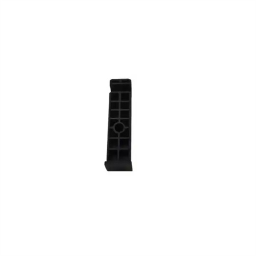
The design of adding glue to air-trapping areas requires precise planning based on the structure of the plastic part and the flow characteristics of the melt. First, the flow state of the melt within the mold cavity must be simulated using mold flow analysis software to accurately identify the location and cause of air entrapment. Air entrapment is typically prone to occur in blind corners of plastic parts, at the junction of thin and thick walls, and in depressions with complex patterns. For these areas, localized increases in material thickness can be employed, such as by providing guide bosses near the air-trapping points to guide the melt to preferentially fill this area and prevent air from being trapped. Alternatively, the material volume can be appropriately increased at the edges of the air-trapping areas to widen the melt’s flow path, allowing air to be smoothly discharged along the cavity wall to the venting grooves. For example, for plastic parts with deep ribs, air entrapment is more likely to occur at the ends of the ribs. The material thickness can be increased near the ends of the ribs to form a sloped transition, promoting air flow toward the venting grooves.
The thickness and extent of the added glue must be strictly controlled. Excessive application can slow the melt flow in this area, creating new air traps or causing sink marks and deformation due to uneven cooling. Excessive application can alter the overall structure and dimensions of the part, impacting its assembly performance and functionality. Generally, the added glue thickness should not exceed 50% of the original part wall thickness and should form a smooth transition with the surrounding structure to avoid abrupt thickness variations. Furthermore, the added glue area should be coordinated with the exhaust system to ensure that extruded air can be promptly discharged from the mold. Typically, the end of the added glue area should be close to the exhaust slot, with a distance of no more than 0.5 mm to ensure effective exhaust.
When adding glue to trapped air areas, the fluidity of the material and the matching of molding process parameters must also be considered. For plastics with poor fluidity, such as polycarbonate and polyoxymethylene, the material thickness in the glue-adding area can be appropriately increased to reduce the flow resistance of the melt; while for plastics with good fluidity, such as polyethylene and polypropylene, the glue-adding thickness should be reduced accordingly to prevent excessive accumulation of the melt in the glue-adding area. In addition, the injection speed and injection pressure also need to be adjusted according to the glue-adding situation. During the filling stage of the glue-adding area, the injection speed can be appropriately increased to allow the melt to quickly fill the glue-adding area and reduce the air retention time; at the same time, with appropriate holding pressure, ensure that the melt in the glue-adding area is fully compacted to avoid defects due to shrinkage.
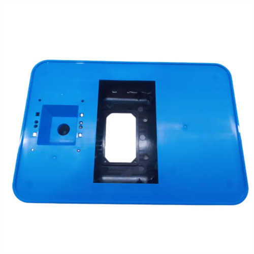
In actual production, the effectiveness of adding glue to air-trapped areas needs to be verified and optimized through mold trials. During mold trials, the rationality of the glue-adding solution can be judged by observing the appearance quality of the air-trapped areas of the plastic part, such as whether there are signs of burning, bubbles, or missing material. If the air-trapping problem persists, the location, thickness, or range of the glue-adding can be further adjusted, or a comprehensive solution can be found by improving the exhaust system and optimizing process parameters. For example, a certain electronic housing plastic part had long suffered from burning caused by air-trapping at the corners. By adding glue to the corners to form an arc transition, increasing the depth of the exhaust groove, and increasing the injection speed by 10%, the air-trapping defect was successfully eliminated, and the product qualification rate increased from 75% to 98%. With the continuous development of mold flow analysis technology, 3D simulation software can be used to preview the melt flow and exhaust conditions after glue-adding, identifying potential problems in advance, reducing the number of mold trials, and improving the accuracy and efficiency of the glue-adding solution.