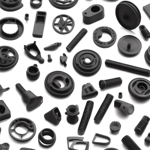
Injection molding inclined top, slider and hydraulic arc core pulling
In injection molds, lifters, sliders, and hydraulic arc core pulling mechanisms are crucial for handling complex part structures (such as undercuts, side holes, and curved protrusions). Each has its own unique operating principles and application scenarios, and together they ensure the smooth demolding of complex parts. The lifter mechanism primarily uses diagonal motion to demold undercuts, while the slider mechanism relies on lateral movement to remove cores from side holes or undercuts. The hydraulic arc core pulling mechanism is suitable for core pulling needs in curved or circular undercuts. The effective use of these three mechanisms can address complex structural issues that traditional demolding methods cannot handle, improving part molding quality and production efficiency.
The inclined ejector mechanism, also known as the inclined push rod mechanism, consists of an inclined ejector rod, a guide slider, a push rod, a return spring, and other parts. Its core is to use the inclined angle of the inclined ejector rod to convert the vertical movement of the push plate into the oblique movement of the inclined ejector rod, thereby completing the core pulling of the undercut part while ejecting the plastic part. The inclined ejector mechanism is suitable for situations where there is a shallow undercut (usually the undercut height is less than 10mm) inside or outside the plastic part, such as the inner clip of a mobile phone case, the boss of an electrical appliance housing, etc. Compared with other core-pulling mechanisms, the inclined ejector mechanism has a compact structure, occupies less mold space, is relatively low in cost, and has a coherent movement, which can complete the core pulling synchronously with the ejection process. However, the inclined ejector mechanism has high requirements for the processing precision of the parts. The clearance between the inclined ejector rod and the guide slider must be strictly controlled. Otherwise, it is prone to jamming or wear, affecting the service life of the mechanism and the core pulling accuracy.
The slider mechanism is the most widely used lateral core-pulling mechanism in injection molds. It consists of a slider, guide groove, inclined guide pins, and a locking block. Its operating principle is that the tilt angle of the inclined guide pin drives the slider to move laterally along the guide groove during mold opening, enabling core pulling of side holes or undercuts. The slider mechanism is suitable for parts with deep undercuts or complex undercuts, such as side holes in automotive parts and lateral protrusions in toys. The slider mechanism offers a large core-pulling distance, typically exceeding 50mm, and a stable core-pulling force, making it suitable for core pulling of even large undercuts. When designing the slider mechanism, the tilt angle of the inclined guide pin (typically 15°-25°) must be appropriately determined to ensure smooth slider movement. Furthermore, the locking block must be designed to ensure accurate slider positioning during mold closing to prevent displacement caused by injection pressure.

A hydraulic arc core pulling mechanism is a hydraulically powered core pulling mechanism primarily composed of a hydraulic cylinder, an arc core, a guide mechanism, and a stopper. It is suitable for core pulling applications involving curved or circular undercuts (such as annular grooves or curved bosses), such as the internal threads of thermos cup lids and curved protrusions on round plastic parts. This mechanism uses a hydraulic cylinder to drive the arc core along an arc-shaped trajectory, achieving core pulling on these undercuts. It offers advantages such as high core pulling force, smooth movement, and precisely controlled core pulling distance. Compared to mechanical core pulling mechanisms, hydraulic arc core pulling mechanisms offer greater flexibility. Pressure and flow regulation in the hydraulic system allows for precise control of core pulling speed and force, making them particularly suitable for large, circular parts or those requiring high core pulling force. However, this mechanism is relatively costly and requires a separate hydraulic system. Furthermore, strict sealing requirements are imposed on the hydraulic components to prevent hydraulic oil leakage that could impact mold performance.
In practical applications, the inclined lift, slider, and hydraulic arc core-pulling mechanisms often need to be combined based on the structural characteristics of the plastic part to address more complex core-pulling requirements. For example, for parts with both internal undercuts and external side holes, a combination of an inclined lift and slider mechanism can be used to handle core pulling at different locations. For parts with curved undercuts and lateral protrusions, a combination of a hydraulic arc core-pulling mechanism and a slider mechanism can be used to ensure coordinated core-pulling action at all locations. When using these mechanisms together, the operating sequence and interference issues of each mechanism must be carefully considered. Properly designed limiters and reset mechanisms ensure that each mechanism does not interfere with the other during the core-pulling and reset processes. Furthermore, the motion parameters of each mechanism, such as core-pulling speed and distance, must be matched to ensure uniform force distribution during the core-pulling process, preventing deformation or damage. The flexible combination and coordinated operation of these three mechanisms can effectively address the core-pulling challenges of various complex plastic parts, providing strong support for injection molding production.