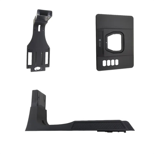
Injection molding push block demoulding mechanism
The injection molding push-block ejection mechanism utilizes a push block to eject the entire part from the mold cavity. Suitable for large, flat, curved, or complex-shaped parts, it features a large ejection area, evenly distributed force on the part, and a low risk of deformation or ejection marks. It plays a vital role in the production of parts such as automotive bumpers, instrument panels, and appliance housings. The push-block ejection mechanism primarily consists of a push block, guide pins, guide sleeves, a push rod, and a push plate. The push block’s shape matches the part’s outer surface contour, forming a tightly fitting molding surface with the mold cavity, ensuring the part’s surface quality. Compared to ejection mechanisms like push rods and push tubes, the push-block ejection mechanism offers greater ejection stability, making it particularly suitable for large parts requiring high surface quality and dimensional accuracy.
The structural design of the ejector block’s ejection mechanism must fully consider the shape and size of the part to ensure uniform ejection force and smooth movement. The ejector block’s molding surface must perfectly conform to the part’s exterior surface, and its machining accuracy must be consistent with the mold cavity. The surface roughness (Ra) must be controlled below 0.8μm to avoid machining marks on the part. The thickness of the ejector block should be determined based on the part’s weight and ejection force, generally no less than 20mm, to ensure sufficient rigidity and prevent bending during ejection. Guide pins and guide sleeves guide the ejector block’s movement, ensuring smooth movement perpendicular to the cavity surface. The clearance between the guide pins and guide sleeves is typically 0.01-0.03mm, with a fit accuracy of H7/h6 to ensure accurate guidance. The number and distribution of ejector pins should be determined based on the size and weight of the ejector block. The ejector pins should be evenly distributed in the non-molding area of the block to ensure balanced force during ejection and prevent tilting.
The working process of the push block demolding mechanism can be divided into three stages: reset, molding, and ejection. The coordinated movements of each stage are key to ensuring the demolding effect. During the reset stage, the push block, under the action of the reset spring or return rod, fits tightly against the mold cavity. The molding surface of the push block and the cavity surface together form the molding space of the plastic part. During the injection molding stage, the melt fills the cavity and cools and solidifies. The push block remains stationary, and together with the cavity, it ensures the shape and dimensional accuracy of the plastic part. During the ejection stage, the injection molding machine’s ejection mechanism drives the push rod forward. The push rod pushes the push plate and push block to move synchronously. The molding surface of the push block contacts the outer surface of the plastic part and applies a uniform ejection force, gradually releasing the plastic part from the mold cavity. When the push block moves to the maximum ejection stroke, the plastic part is completely released from the cavity. The ejection mechanism then drives the push block to reset and enter the next production cycle. During the ejection process, the relative movement of the push block and the cavity must remain smooth to avoid scratches or deformation on the surface of the plastic part due to deviation in the motion trajectory.
The push block demoulding mechanism has obvious targeting in its applicable scenarios. It is mainly suitable for large, flat, curved or complex-shaped plastic parts, especially for those plastic parts that are prone to deformation or ejection marks when demoulding with a push rod. For plastic parts with deep cavities or complex concave-convex structures, the push block can form a large-area contact with the surface of the plastic part, disperse the ejection force, and avoid local stress concentration that causes damage to the plastic part. When producing long plastic parts such as car bumpers, the push block can be designed as a multi-section structure, driven separately by multiple push rods to ensure that the various parts of the push block move synchronously and avoid warping of the plastic part due to uneven force. The disadvantages of the push block demoulding mechanism are that the structure is relatively complex, the mold manufacturing cost is high, and the movement of the push block requires a large space. Therefore, it is rarely used in the production of small plastic parts or plastic parts with simple structures. Usually, a demoulding mechanism with a simple structure such as a push rod is preferred.
The installation, commissioning, maintenance, and troubleshooting of the push block demolding mechanism require professional skills and extensive experience to ensure its long-term stable operation. During installation, the clearance between the push block and the cavity must be precisely adjusted to ensure that the push block fits tightly against the cavity when in the reset state, with a clearance of no more than 0.02mm to prevent melt overflow. At the same time, the coaxiality of the guide pin and guide sleeve must be ensured, and the motion trajectory of the push block must be corrected using a dial indicator to ensure that the direction of motion of the push block is perpendicular to the cavity surface. During debugging, the ejection speed and pressure must be gradually adjusted, and the demolding status of the plastic part must be observed. The ejection speed is generally controlled at 20-50mm/s, and the ejection pressure should be just enough to eject the plastic part without deformation. During routine maintenance, the molding surface of the push block and the mating surfaces of the guide pin and guide sleeve must be regularly cleaned to remove residual plastic debris and oil stains. Grease should be added regularly to reduce movement friction. If the pusher block becomes stuck during production, the guide pins and sleeves should be inspected for wear or impurities, and repaired or cleaned. If indentations appear on the surface of the plastic part, this may be due to excessive clearance between the pusher block and the mold cavity or impurities on the pusher block surface. The clearance should be readjusted or the pusher block surface cleaned. Through scientific management and maintenance, the pusher block demolding mechanism can effectively improve the production quality and efficiency of large, complex plastic parts.