The injection molding slider locating clamp is a key component used to secure the slider in the side core-pulling mechanism. Its function is to lock the slider in the working position when the mold is closed, preventing injection pressure from causing the slider to move. When the mold is opened, it releases with the slider’s movement, ensuring smooth core-pulling. This locating clamp is widely used in molds for plastic parts with side holes and undercuts. For example, if the slider in an automotive connector mold is not securely positioned, injection pressure can cause a 0.1-0.3mm offset, resulting in dimensional deviations in the side holes of the plastic part. The performance of the slider locating clamp depends on its structural design, material selection, and specifications. The appropriate model should be selected based on the slider weight, core-pulling force, and travel range to ensure positioning accuracy (≤0.02mm) and sufficient locking force (≥1.5 times the core-pulling force).
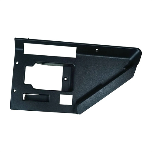
The injection molding slider retaining clamp consists of a fixed base, a movable chuck, a spring, and an adjustment screw, achieving positioning through mechanical self-locking. The fixed base is mounted on either the movable or fixed platen, and the movable chuck is connected to the fixed base via a pin. The spring provides clamping force, keeping the chuck in contact with the slider’s retaining groove, and the adjustment screw adjusts the chuck’s preload. When the slider is in the closed mold position, the chuck engages the slider’s V- or U-shaped retaining groove, creating a mechanical self-locking mechanism. The locking force increases with injection pressure, preventing the slider from retreating. During mold opening, the slider is driven by an inclined guide post, and the slider’s thrust overcomes the spring force, opening the chuck and releasing the lock. During core pulling, the chuck maintains contact with the slider surface, providing guidance. Some high-end retaining clamps also feature a cushioning device (such as a rubber pad) to reduce the impact noise when the slider is in place. For example, in precision gear molds, a cushioned retaining clamp can reduce impact noise from 85 decibels to below 70 decibels.
The specifications of a slider locating clamp must match the slider size and core pulling force, primarily including locking force, clamping range, and installation dimensions. Locking force is a key parameter. The small locating clamp (model ST-16) has a locking force of 5-10kN and is suitable for lightweight molds with sliders weighing less than 5kg, such as side core pulling in mobile phone cases. The medium locating clamp (model ST-25) has a locking force of 15-30kN and is suitable for sliders weighing 5-15kg, such as in molds for household appliance components. The large locating clamp (model ST-40) has a locking force of 50-80kN and is suitable for heavy sliders (>15kg), such as side core pulling in automotive bumpers. The clamping range refers to the width of the slider locating slot that the clamp head can accommodate, typically ranging from 8-30mm. For example, the ST-20 locating clamp has a clamping range of 10-20mm, which can be fine-tuned by ±1mm using an adjustment screw. The installation dimensions include the length (50-120mm), width (30-80mm) and height (25-60mm) of the fixing base, which must match the thickness of the mold template to ensure a secure installation. For example, when the template is 50mm thick, choose a positioning clamp with a height of 30mm to avoid protruding from the template surface.
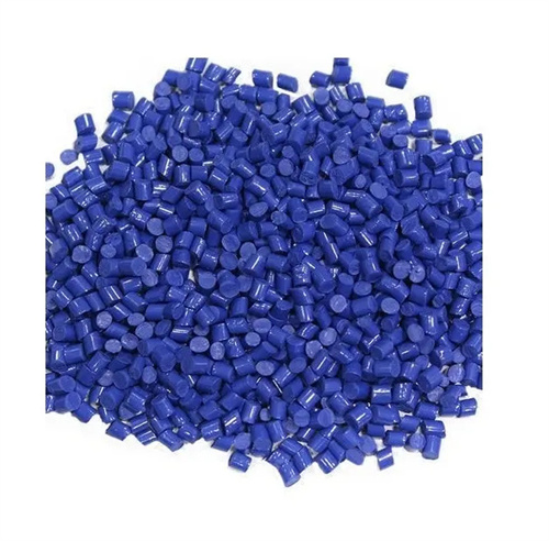
The material and heat treatment of the slider locating clamp determine its wear resistance and service life. The fixed base and movable chuck must be made of high-strength alloy steel. SCM440 alloy structural steel is commonly used. After carburizing and quenching, it achieves a surface hardness of 58-62 HRC and a core hardness of 30-35 HRC. This combines high strength and toughness to prevent chuck breakage. The spring is made of music wire (SWP-B) with a diameter of 1.5-3mm and an elastic limit of ≥1600MPa, ensuring a force decay of ≤10% after long-term use (service life of ≥100,000 cycles). The sliding contact surface of the locating clamp must be ground to a roughness of Ra 0.8μm or less and lubricated with high-temperature grease (temperature resistant >150°C) to reduce friction and wear. Some locating clamps feature a nitrided surface (nitrided layer thickness 0.1-0.2mm) to further enhance wear resistance, making them suitable for high-volume mold production (>500,000 mold runs).
The selection and installation of the slider locating clamp must adhere to specific specifications to ensure reliable positioning. When selecting a clamp, calculate the lateral force acting on the slider (typically 10%-20% of the injection pressure) and select a clamp with a locking force greater than 1.5 times the lateral force. For example, if the lateral force is 20kN , a clamp with a force of 30kN or higher is required . The installation location should be close to the slider’s center of gravity or the load point, and ≤ 100mm from the inclined guide post to avoid torque that could cause positioning deviation. The mounting base is secured to the template using hexagon socket head cap screws (grade 8.8 ) with a diameter of 6-10mm and a tightening torque of 20-50N · m to ensure no looseness. After installation, check the fit of the clamp in the locating slot for a clearance of ≤ 0.05mm . Manually pushing the slider should be smooth and free of sticking, and provide clear locking feedback when in position. During mold trials, the slider displacement should be tested at maximum injection pressure. This should be ≤0.01mm. Otherwise, the number of retaining clamps should be increased or a larger model should be used. During routine maintenance, debris should be regularly cleaned from the retaining clamp surface. Grease should be added every 10,000 molds to ensure long-term stable operation.