Injection molded slider type distance mechanism
The injection molding slider-type spacing mechanism is a key device for controlling the sequential opening of the mold’s parting surfaces. This mechanism achieves fixed-distance parting through the sliding of the slider, ensuring that the different parting surfaces open in a preset sequence during the mold opening process. This facilitates core pulling, part removal, or the automatic shedding of solids from the gating system. This mechanism is widely used in molds with multiple parting surfaces, such as three-plate molds, two-color molds, and molds with complex core pulling. For three-plate molds with two cavities, the use of a slider-type spacing mechanism improves the accuracy of the parting sequence from 95% to 100%, eliminating mold damage caused by parting errors. The core of the slider-type spacing mechanism is to limit the parting distance through the cooperation of the slider, guide posts, and tie rods. Its design must be determined based on the parting force, spacing, and mold structure to ensure precise movement and rapid response to meet the requirements of automated production.
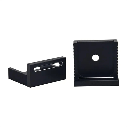
The basic structure of a slider-type distance-fixing mechanism consists of a distance-fixing slider, a guide post, a spring, a stopper, and a tie rod. These components work together to achieve the distance-fixing function. The distance-fixing slider is installed in a slot in the movable or fixed platen and can slide horizontally. One end of the slider is connected to the spring, and the other end has a bevel or hook that engages with a slot in the tie rod. The tie rod is fixed to the other platen and moves with the mold opening and closing. The stopper limits the slider’s sliding travel. In the closed mold state, the spring pushes the slider into the tie rod’s slot, locking the two platens. During mold opening, when the parting force exceeds the spring force, the tie rod drives the slider, compressing the spring and releasing the slider from the slot. At this point, the stopper limits the slider’s maximum travel, ensuring a precise parting distance (tolerance ≤ 0.5mm). For example, if a mold requires a 100mm parting line, the slot on the tie rod is positioned 100mm from the starting point. When the mold is opened to 100mm, the slider releases the slot, completing the first parting, and the mold then continues to open to the second parting line.
Slider-type spacer mechanisms can be categorized by locking method into hook, ramp, and ball types, suited to different working conditions. Hook-type spacer mechanisms utilize the slider’s hook to engage the tie rod’s groove for locking, offering high locking force ( 5-20kN). They are suitable for molds with high parting forces, such as large appliance housing molds. The hook’s contact area should be ≥20mm² to prevent wear from long-term use. Inclined-type spacer mechanisms utilize the inclined contact between the slider and tie rod. The resulting force from the inclined surface retracts the slider during mold opening, resulting in high spacing accuracy (±0.3mm). They are suitable for small and medium-sized precision molds, such as mobile phone component molds. The ramp angle is typically 15°-25°. A smaller angle increases locking force but reduces sensitivity, while a larger angle has the opposite effect. Ball-type spacer mechanisms achieve positioning by embedding a steel ball in the tie rod’s annular groove. They offer fast response (<0.1 second) and are suitable for molds with high-speed openings, such as bottle cap molds. However, their locking force is lower (<5kN) and requires a spring to increase preload.
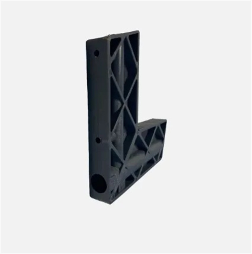
The design parameters of a slider-type spacer mechanism must be determined based on the mold’s parting requirements, primarily including the spacer distance, locking force, and travel. The spacer distance refers to the required opening distance of the parting surface and is determined by the core pulling stroke or the space available for part removal. For example, for a core pulling stroke of 50mm, the spacer distance must be ≥60mm to ensure complete core pulling. The locking force must be greater than the tensile force acting on the parting surface (typically 5%-10% of the injection pressure). For example, for a mold with an injection pressure of 100MPa, the parting force is approximately 5-10kN, so a spacer mechanism with a locking force ≥10kN is required. The slider’s travel should be 10-30mm to ensure complete release from the tie rod slot. Too short a stroke will result in incomplete release, while too long will increase mold size. For example, the ST-30 spacer mechanism has a slider travel of 20mm, which is suitable for most small and medium-sized molds. Furthermore, the mechanism’s installation space must match the mold plate dimensions, typically 40-100mm in width and 30-80mm in height, to avoid interference with other components.
The installation, commissioning, and maintenance of slider-type distance mechanisms are crucial to ensuring their performance. During installation, ensure that the coaxiality error between the distance slider and the tie rod is ≤0.1mm, and the parallelism error of the slider’s sliding groove is ≤0.05mm/m. Failure to do so will result in movement jamming. The spring compression must be adjusted to the appropriate preload. Too little compression will result in insufficient locking force, while too much compression will increase mold opening resistance. Typically, the compression is 20%-30% of the free length. For example, for a spring with a free length of 50mm, compression to 40-35mm is appropriate. During the commissioning phase, observe the mechanism’s unlocking timing in slow motion to ensure accurate unlocking at the preset distance. If the error exceeds 1mm, adjust the tie rod slot position or spring preload. During mold trials, test opening and closing the mold multiple times to check for unusual noises or jamming. The distance consistency should be ≤±0.5mm. During daily maintenance, it is necessary to regularly clean the oil and debris in the slider groove, add lubricating oil once a month, check whether the spring is fatigue-failed, and the wear of the pull rod and slider. If any problems are found, replace them in time to ensure that the service life of the mechanism reaches more than 500,000 times.