Design of injection molding positioning system
The injection molding positioning system is a core structure that ensures mold closing accuracy and part dimensional stability. Through the coordination of guide pins, guide bushings, and locating pins, it ensures precise alignment between the movable and fixed molds during mold closing, preventing flash, dimensional deviations, and mold damage caused by misalignment. The accuracy of the positioning system directly impacts the dimensional tolerance of the plastic part. For example, for precision parts with tolerances of ±0.05mm, the positioning system’s clearance must be controlled within 0.01-0.02mm. This system is widely used in various injection molds and is particularly important in multi-cavity, precision , and large molds. For example, a high-precision positioning system for a mobile phone casing mold can control the dimensional deviation of a multi-cavity part to within ±0.03mm. The design of the injection molding positioning system requires determining the component type, quantity, and mating accuracy based on the mold type, part precision requirements, and production batch size. The system fulfills the multiple functions of guiding, positioning, and withstanding lateral forces.

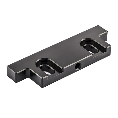
The core components of the injection molding positioning system include the guide mechanism, positioning device, and auxiliary positioning structure. The guide mechanism primarily consists of a guide pin and a guide sleeve. The guide pin is fixed to either the movable or fixed mold, while the guide sleeve is mounted on the other mold plate. During mold closing, the guide pin inserts into the guide sleeve, guiding the mold for accurate closing. The guide pin is typically made of 20CrMnTi, quenched (hardness 58-62 HRC), and ground to a surface accuracy of Ra0.4μm with a diameter tolerance of h6. The guide sleeve is made of bronze or cast iron with an inner diameter tolerance of H7 and a clearance of 0.01-0.03mm between the guide pin and the guide sleeve, ensuring precise guidance. Positioning devices are used to precisely control the relative position of the movable and fixed molds. Common positioning devices include locating pins and holes, tapered surface positioning, and combined positioning. The diameter of the locating pins is typically 10-20mm with an M6 tolerance, while the tolerance of the holes is H7. The clearance is 0.005-0.015mm, making them suitable for small and medium-sized precision molds. Tapered surface positioning, which uses conical surfaces on the movable and fixed molds, can achieve positioning accuracy within 0.005mm, making it suitable for large molds or applications with high requirements. Auxiliary positioning mechanisms, including guides for the reset rod and the pull rod, help ensure platen parallelism.
The layout of the positioning system should be designed based on the mold size and cavity distribution to ensure balanced guidance and reliable positioning. Small and medium-sized molds typically use four guide pins, located at the four corners of the mold plate. The distance between the guide pins and the edge of the mold plate should be 1.5-2 times their diameter. For example, a 20mm diameter guide pin should be 30-40mm from the edge. Large molds (with mold plates larger than 1000mm) require an increased number of guide pins (6-8), with additional guide pins located in the center of the mold plate to prevent deformation during mold closing. The positioning system of multi-cavity molds should be symmetrical with the cavity distribution, and guide pins should be placed on the outside of the cavities to avoid affecting the cavity layout. For example, a bottle cap mold with eight cavities would have four 16mm diameter guide pins at the four corners and two 20mm diameter guide pins in the center to ensure even force distribution across the cavities during mold closing. The positioning device should be placed close to the mold cavity. For large molds, four sets of tapered surfaces can be installed around the cavity. Each set of tapered surfaces should have a contact area of ≥50 cm² to withstand lateral forces during mold closing and prevent cavity misalignment. Furthermore, the guide pin should be long enough to ensure that 1/3 of its length remains within the guide sleeve when the mold is opened to its maximum stroke, preventing the pin from separating from the sleeve and causing guide failure.
Precision control of the positioning system must be implemented throughout the entire design, processing, and assembly process. The tolerance levels of each component must be clearly defined during the design phase. The clearance between the guide pin and guide sleeve is determined based on the precision of the plastic part, with a tolerance of 0.01-0.02mm for precision plastic parts and 0.02-0.05mm for standard plastic parts. During processing, the straightness error of the guide pin must be ≤0.01mm/m, the coaxiality error of the guide sleeve ≤0.005mm, and the locating pin and locating hole must use a transition fit (H7/m6) to ensure accurate positioning and easy disassembly. During assembly, precision tooling must be used to ensure the perpendicularity of the guide pin and the template (error ≤0.01mm/m). The height difference between multiple guide pins must be ≤0.02mm to avoid additional torque during mold closing. For example, during assembly of the positioning system for a precision gear mold, the guide pin position is adjusted using a three-dimensional coordinate measuring machine to ensure that the perpendicularity error between the guide pin axis and the mold plate plane is less than 0.005mm, and the coaxiality error between the guide sleeve and the mold plate is less than 0.003mm. Ultimately, the pitch error of the plastic part is controlled within 0.01mm. Furthermore, the positioning system requires wear resistance treatment. The guide pin surface can be nitrided (nitriding layer thickness 0.1-0.2mm) to increase surface hardness (>800HV) and extend service life.
Maintaining and improving the positioning system is critical to ensuring long-term accuracy. During daily production, guide pins and guide bushings should be regularly cleaned of oil and debris to prevent impurities from entering the clearance and causing wear or seizure. Lubricant (such as lithium-based grease) should be added daily to maintain smooth guiding. Guide pins and bushings should be regularly inspected for wear. When the clearance exceeds 50% of the initial value, they should be replaced. For example, a guide pin and bushing with an initial clearance of 0.02mm must be replaced when wear drops to 0.03mm. For molds with large production runs (>1 million molds), removable guide pins and bushings can be used for easier replacement and maintenance. For improvements, self-lubricating guide bushings (such as oil-impregnated bronze) can be used to reduce lubrication requirements, or hard chrome plating (0.01-0.02mm thick) can be applied to the guide pins to improve wear resistance. For high-temperature molds (such as engineering plastics molds), heat-resistant positioning components are required. Guide pins are made of 316 stainless steel, and guide sleeves are made of graphite bronze. This ensures stable fit accuracy even in temperatures of 150-200°C. Through scientific design, precision machining, and standardized maintenance, the injection molding positioning system can achieve stable operation for over a million mold cycles, providing reliable assurance of part quality.