Multi-point hot runner injection mold
A multi-point hot runner injection mold is a highly efficient molding device that simultaneously injects molten plastic into multiple cavities via multiple hot runner nozzles. Its core principle is to utilize a manifold to evenly distribute the melt to each gate, enabling simultaneous filling and curing of multi-cavity plastic parts, significantly improving production efficiency and product consistency. Compared to single-point hot runner molds, multi-point structures can adapt to the production needs of multiple cavities per mold. They are particularly suitable for the mass production of small plastic parts such as bottle caps, connectors, and electronic components. For example, a 32-cavity bottle cap mold using a multi-point hot runner saw a 50% increase in production efficiency and a 30% reduction in material waste compared to a cold runner mold. The design of a multi-point hot runner requires precise control of the temperature and pressure balance of each nozzle to ensure consistent filling speed and pressure holding effect in each cavity. Its performance directly impacts the dimensional accuracy and quality stability of multi-cavity plastic parts.
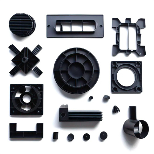
A multi-point hot runner injection mold consists of a main nozzle, a manifold, hot nozzles, heaters, a temperature control system, and a runner plate cooling system. The main nozzle connects to the injection molding machine barrel and directs the melt into the manifold. The manifold is equipped with internal runners, designed in an X-, H-, or radial pattern depending on the number and distribution of cavities, to ensure even distribution of the melt to each hot nozzle. The runner diameter is typically 8-12mm, with a surface roughness of Ra below 0.4μm to reduce flow resistance. The number of hot nozzles matches the number of cavities and is mounted directly on the manifold. Their heads extend deep into the cavities, enabling runnerless injection molding. Common types include open, needle-valve, and latent. The needle-valve hot nozzle uses a pneumatic cylinder to control the opening and closing of the needle valve, eliminating gate marks and making it suitable for parts requiring high aesthetics. Heaters are divided into manifold heaters and nozzle heaters. The manifold utilizes a wraparound heating belt with a power density of 15-20W/cm², while the nozzles utilize internal heating rods with a power density of 20-30W/cm² to ensure uniform melt temperature within the runners. The temperature control system needs to be equipped with an independent temperature controller for each hot nozzle with a control accuracy of ±1°C to avoid uneven filling due to temperature differences.
The runner and nozzle layout design of a multi-point hot runner must meet the requirements of melt flow balance. Runner lengths should be as consistent as possible, with the distance difference between each hot nozzle and the main nozzle ≤5mm to ensure uniform melt pressure loss within each runner. For example, a 16-cavity connector mold uses a radial manifold, with 16 hot nozzles evenly distributed around a 200mm diameter circle. The deviation in runner length is controlled within 3mm, and the filling time difference is ≤0.2 seconds. The spacing between hot nozzles should be determined according to the cavity layout, typically ≥30mm, to avoid thermal interference between nozzles and facilitate installation and maintenance. For asymmetric cavity layouts, melt flow can be balanced by adjusting the runner diameter (e.g., using a larger diameter for the long runner) or by setting a throttle valve. For example, in an asymmetric mold with 8 cavities, increasing the long runner diameter from 8mm to 10mm can achieve consistent filling times for each cavity. In addition, the gate of the hot nozzle needs to be located at the thick wall or geometric center of the plastic part to ensure smooth flow of the melt in the cavity and reduce defects such as weld marks and bubbles.
The process parameter setting for multi-point hot runner molds requires coordinated control of temperature, pressure, and speed. The hot runner temperature is typically 5-10°C higher than the barrel temperature. For example, for PP, the barrel temperature is 180-200°C, while the hot runner temperature is 185-210°C. This ensures that the melt does not cool and solidify within the manifold and nozzle. The injection pressure must be 10%-15% higher than that of a cold runner mold to compensate for pressure losses in multiple runners. For example, the injection pressure of an ABS plastic part in a cold runner mold is 80MPa, but this pressure must be increased to 88-92MPa with a multi-point hot runner. The injection speed is controlled in stages, starting with a low speed (20-30mm/s) to prevent melt ejection. After filling 50% of the cavity volume, the speed is increased to 50-70mm/s to ensure rapid filling and minimize cooling variations. Holding pressure and time need to be adjusted based on the filling conditions of each cavity. Typically, holding pressure is 60%-70% of the injection pressure, and holding time is 10%-20% shorter than in cold runner molds, as hot runners can continuously feed the cavity. Furthermore, the hot nozzle and manifold runners require regular cleaning to remove material buildup and carbides. This cleaning cycle is determined by the production batch (typically every 50,000 molds) to prevent blockages that could affect melt flow.
The application and maintenance of multi-point hot runner molds require careful consideration of several key points. They are suitable for high-volume (annual production capacity over 1 million pieces) and small-size (weight less than 50g) multi-cavity production in a single mold, such as medical supplies and electronic components, significantly reducing production costs. During the commissioning phase, mold flow analysis software should be used to simulate the filling process of each cavity and optimize the runner and nozzle layout. During mold trials, pressure sensors should be used to measure the filling pressure of each cavity, ensuring a ≤5% difference. During routine maintenance, the heater’s operating status should be checked to avoid local overheating or underheating. The thermostat should be calibrated regularly to ensure that the temperature displayed is consistent with the actual temperature (deviation less than ±2°C). For needle-valve hot nozzles, the needle valve’s movement should be regularly checked for flexibility and impurities should be removed to prevent gating errors caused by sticking. During shutdowns, the hot runner temperature should be lowered to below 150°C before turning off the power to prevent component damage caused by thermal expansion and contraction. With proper application and maintenance, multi-point hot runner molds can achieve a service life of over 1 million cycles, providing strong support for efficient mass production.