The reasons why shrinkage holes in PC plastic parts are difficult to solve and their solutions
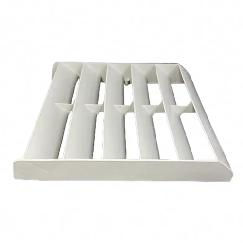
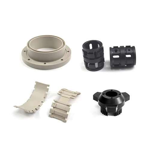
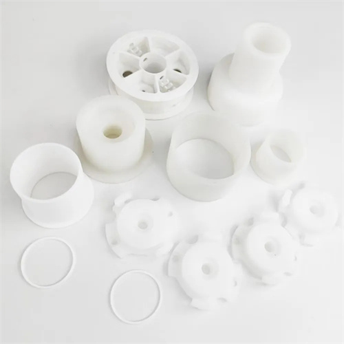
As a high-performance engineering plastic, PC (polycarbonate) is widely used in electronics, automotive, and medical devices due to its excellent mechanical properties, heat resistance, and transparency. However, shrinkage holes often present a production challenge during PC injection molding. These holes not only affect the appearance of the plastic part but also reduce its structural strength, leading to potential cracking and deformation during use. Due to PC’s high melt viscosity and rapid cooling rate, resolving this shrinkage problem often requires multi-dimensional analysis and system optimization, otherwise the problem is prone to recurrence.
PC plastic parts is closely related to the material’s properties. PC ‘s molecular structure contains numerous benzene rings, resulting in a high viscosity in its molten state (typically between 1,000 and 10,000 Pa · s ) and poor fluidity. During the injection molding process, the melt has difficulty quickly filling every corner of the mold cavity. This is especially true for parts with uneven wall thicknesses, where insufficient melt replenishment can easily lead to shrinkage cavities in thicker areas. Furthermore, PC has a high specific heat capacity and a high volumetric shrinkage rate during cooling (approximately 0.5%-0.7% ). If the melt is not adequately replenished during solidification, vacuum voids can form within the part. Furthermore, PC is extremely moisture-sensitive. Inadequate drying of the raw material can cause hydrolysis during melting, leading to a decrease in molecular weight, further reducing melt fluidity and exacerbating shrinkage cavities. This is a key reason shrinkage cavities are difficult to resolve—the material’s inherent properties impose stringent molding conditions, and even the slightest parameter fluctuation can trigger shrinkage cavities.
Improper mold design is another key factor that makes shrinkage voids in PC materials difficult to eliminate. The location and number of mold gates directly influence the melt’s flow path within the mold cavity and the filling rate. If the gates are located far from thick-walled areas of the part, the melt will have already begun to cool and solidify by the time it reaches these areas, significantly reducing its fluidity and preventing effective shrinkage feeding. Insufficient gates can also lead to excessive pressure loss during the filling process, making it difficult to transmit sufficient holding pressure to the areas requiring feeding. Furthermore, design flaws in the mold cooling system can exacerbate shrinkage voids. Uneven cooling channels and slow cooling rates in thick-walled areas can cause the melt in these areas to continue shrinking even after the holding phase ends. By this time, the melt outside has solidified, making feeding impossible, ultimately forming shrinkage voids. For complex parts, poor mold venting prevents timely evacuation of air from the cavity, hindering melt filling and causing shrinkage voids in localized areas due to material shortages. These shrinkage voids are often hidden and difficult to completely eliminate by adjusting process parameters.
Improper process parameter settings are a major contributing factor to recurring shrinkage problems. Insufficient injection and holding pressures are common root causes. The high viscosity of PC materials requires higher injection pressures (typically 80-150 MPa) to ensure the melt fills the cavity. Insufficient pressure can lead to incomplete filling in thick-walled areas, which in turn causes shrinkage. Setting the holding pressure and holding time is equally critical. The cooling and shrinkage of PC materials requires a sufficient holding period to replenish the melt. If the holding pressure is too low or the holding time is too short, it will not offset the shrinkage in thick-walled areas, leading to shrinkage. Furthermore, improper control of melt and mold temperatures can exacerbate shrinkage. Excessively low melt temperatures reduce fluidity and increase filling resistance, while excessively high temperatures can cause PC material degradation and the formation of bubbles, which can compound with shrinkage. Excessively low mold temperatures can cause the melt to solidify rapidly on the cavity surface, forming a hard shell that hinders internal melt feeding. Insufficient mold temperature is a common cause of shrinkage that is difficult to resolve, especially for thick-walled parts.
The stubborn shrinkage problem in PC materials requires systematic solutions. During material pretreatment, PC material drying conditions must be strictly controlled, typically at 120-130°C for 4-6 hours to keep the moisture content below 0.02% to prevent hydrolysis from affecting melt flow. The dried material should be sealed to prevent reabsorption of moisture and ensure stable material properties during the injection molding process.
In terms of mold optimization, the gate and cooling system should be rationally designed based on the part structure. For thick-walled parts, direct gates or fan gates close to the thick-walled areas are preferred to shorten the melt flow path and reduce pressure loss. If necessary, the number of gates should be increased to ensure that all areas are fully filled and compensated for shrinkage. The cooling system design should follow the principle of “strong cooling in thick-walled areas and weak cooling in thin-walled areas.” Increasing the number of cooling water channels or using conformal water channels in thick-walled areas can accelerate the cooling rate in these areas while avoiding shrinkage differences caused by uneven cooling. In addition, venting grooves (depth controlled at 0.01-0.02mm) should be added to the last area of the cavity to ensure smooth gas discharge and eliminate shrinkage holes caused by trapped air.
Fine-tuning process parameters is key to resolving shrinkage issues. During the injection molding stage, the melt temperature should be appropriately elevated (typically 280-320°C) to enhance the fluidity of the PC material. This, combined with higher injection pressure and speed, ensures that the melt quickly fills the mold cavity. During the holding phase, a “staged holding” strategy should be employed. Initially, the holding pressure should be set to 80%-90% of the injection pressure for 1-2 seconds to rapidly replenish the melt. Subsequently, the pressure should be reduced to 60%-70%, and the holding time extended (5-15 seconds, depending on the thickness of the part) to slowly feed the melt and offset cooling shrinkage. The mold temperature should be controlled between 80-120°C. This elevated mold temperature slows the solidification of the melt surface, creating conditions for internal melt feeding. Furthermore, the cooling time can be appropriately extended to ensure full solidification before demolding, minimizing shrinkage caused by subsequent shrinkage. Only through the coordinated optimization of materials, molds, and processes can the persistent problem of shrinkage in PC materials be effectively addressed and the consistency of part quality improved.