Injection molding sloping top base design
The injection molding lift base is a crucial component of the lift mechanism. Its primary function is to support the lift rod, guide its trajectory, and transmit the push plate’s driving force to it. Therefore, the rationality of the lift base’s design directly impacts the mechanism’s operational stability and core-pulling accuracy. The design of the lift base must comprehensively consider factors such as the lift rod’s tilt angle, core-pulling distance, and stress conditions to ensure it possesses sufficient strength, rigidity, and guiding accuracy to meet the lift mechanism’s operational requirements. A scientifically sound lift base design can effectively reduce wear on the lift mechanism, extend its service life, and ensure the quality of the core-pulling process of the plastic part.
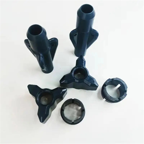
The structure of the lifter base must be designed based on the size of the lifter rod, the tilt angle, and the mold installation space. Common structures include integral and modular types. The integral lifter base integrates the base and guide slider into a single unit, offering advantages such as compact structure, good rigidity, and easy installation. It is suitable for applications with small lifters and small tilt angles (usually less than 20°). The modular lifter base consists of a base body, guide slider, wear-resistant plate, and other parts, each of which can be machined and replaced individually. It is suitable for applications with larger lifters, large tilt angles (greater than 20°), or high core-pulling forces. The guide slider of the modular lifter base is typically made of wear-resistant materials (such as bronze or high-strength plastic), which can reduce friction and wear with the lifter rod and improve the mechanism’s movement flexibility. When selecting a structural form, it is necessary to consider the actual mold conditions and minimize manufacturing costs and processing difficulty while ensuring performance.
The guiding accuracy of the lift base is one of the key design indicators, which is mainly guaranteed by the matching accuracy between the base and the lift rod, and between the base and the push plate. The matching between the lift base and the lift rod usually adopts a clearance fit. The matching clearance needs to be determined according to the size and inclination angle of the lift rod, which is generally 0.02-0.05mm. It not only ensures that the lift rod can move flexibly, but also prevents the lift rod from shaking due to excessive clearance, which affects the core pulling accuracy. The connection between the base and the push plate must be firm and reliable. Screw fastening or locating pin positioning is usually used to ensure the accurate position of the base on the push plate, and avoid the lift rod movement trajectory deviating from the design requirements due to the offset of the base. In addition, a guide groove or guide hole needs to be set on the lift base to cooperate with the guide boss or guide rod on the lift rod to further improve the guiding accuracy and prevent the lift rod from rotating or offsetting during movement.
The strength and rigidity design of the lift base must take into account the forces applied during the core pulling process to avoid deformation or damage to the base due to excessive forces. During the core pulling process, the lift rod is subjected to a reaction force from the plastic part, which is transmitted to the lift base. Therefore, the material selection and cross-sectional design of the base are crucial. The lift base is typically constructed from high-quality carbon tool steel (such as T8A, T10A) or alloy tool steel (such as Cr12, Cr12MoV) and quenched to a hardness of HRC50-55 to enhance its strength and wear resistance. The base’s cross-sectional dimensions must be calculated based on the core pulling force to ensure that, under maximum core pulling force, deformation remains within the allowable range (typically less than 0.01mm). For higher core pulling forces, reinforcing ribs can be added to the base, or the base can be manufactured using a monolithic forging process to improve its overall rigidity.
The installation and commissioning of the lift base are also crucial to ensuring the performance of the lift mechanism. Before installing the lift base, check the machining accuracy of the base, such as the parallelism and perpendicularity of the guide grooves and the flatness of the mounting surface, to ensure that they meet design requirements. During installation, use precision measuring tools such as a dial indicator to calibrate the base’s position to ensure that the guide direction of the base aligns with the tilt angle of the lift rod, with a deviation of no more than 0.02mm. During commissioning, observe the movement of the lift rod within the base to ensure there is no binding or unusual noise, and that the core pulling and return movements are smooth. If movement is not smooth, check the appropriate clearance and the guide grooves for impurities or wear, and make appropriate adjustments and repairs. Additionally, apply high-temperature resistant grease to the mating surfaces of the lift base and lift rod to reduce friction and wear, thereby increasing the mechanism’s flexibility and service life. Through scientific design, precise machining, and meticulous installation and commissioning, the lift base provides reliable support for the stable operation of the lift mechanism.