Deep cylinder plastic parts exhaust
Deep cylindrical plastic parts are representative complex products in injection molding. Their height is usually greater than 1.5 times their diameter, such as water cups, pen holders, motor housings, etc. During molding, these products are prone to gas accumulation due to the deep cavity and long melt flow path, leading to defects such as material shortages, scorch marks, and bubbles. The design of the exhaust system is crucial to the quality of deep cylindrical plastic parts. Based on their structural characteristics, multi-dimensional exhaust measures must be taken to ensure that the air and volatiles in the cavity are discharged in a timely manner. The exhaust design of deep cylindrical plastic parts must be combined with the melt flow characteristics, mold structure and molding process to ensure exhaust efficiency while avoiding the generation of flash or affecting the appearance of the product. This is one of the difficulties in mold design.
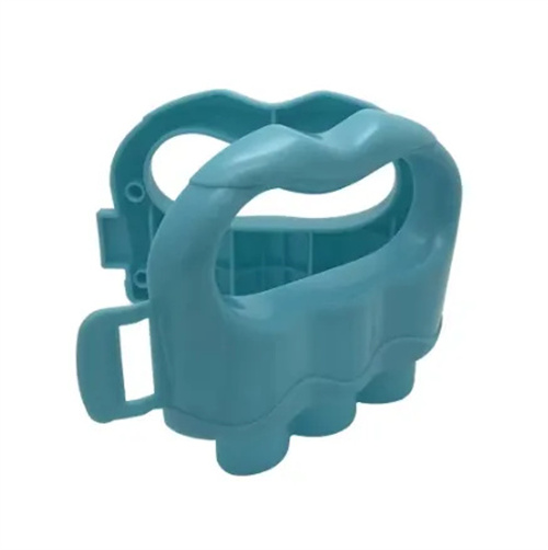
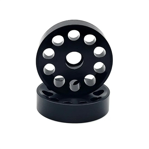
The difficulty in venting deep cylindrical plastic parts primarily stems from their unique structural morphology, requiring specific analysis of the location and causes of gas accumulation. When filling a deep cylindrical cavity, the melt typically feeds from the bottom or sidewalls, flowing upward along the walls. Gas is squeezed toward the mouth or bottom corners, forming closed air pockets. Due to the high walls, the melt encounters significant resistance and slows flow, making it difficult for gas to escape with the melt. This is especially true around the flange at the mouth or the rounded corners at the bottom, where high-pressure gas pockets can easily form. Deep cylindrical parts typically have a relatively uniform wall thickness, allowing the melt front to advance smoothly. Gas is trapped within the melt, making it difficult to escape through the parting surface. Inadequate venting can compress the gas, generating high temperatures that can cause surface scorching or melt degradation. Furthermore, the shallow draft angle of deep cylindrical parts and the large contact surface between the mold and the part can also hinder gas evacuation. For example, in a 100mm tall and 50mm diameter PP water cup, melt is fed from the bottom center, where gas tends to accumulate at the edge of the cup mouth. Inadequate venting can result in material loss or scorching at the cup mouth.
Venting at the parting surface is the most fundamental method for venting deep cylindrical plastic parts. Venting grooves should be strategically placed at key locations where gas accumulates. For deep cylindrical parts with flanges at the mouth of the cup, venting grooves should be located on the flange’s parting surface, evenly distributed around the circumference. Each venting groove should be 10-15mm long and 5-8mm wide. The depth is determined by the plastic viscosity: 0.02-0.03mm for low-viscosity plastics (such as PE and PP) and 0.03-0.05mm for high-viscosity plastics (such as PC and ABS). The venting grooves should extend outward from the edge of the cavity, and the extended portion can be deepened to 0.5-1mm to facilitate rapid gas discharge. For deep cylindrical parts without flanges, an annular venting groove can be created at the parting surface of the cup mouth, or four to six venting notches can be placed symmetrically to ensure gas discharge from multiple points. Venting holes should be located at the ends of the venting grooves to direct the gas outside the mold to prevent it from circulating inside. The venting of the parting surface must be coordinated with the mold guide mechanism to avoid conflicts between the venting groove and the guide pin and guide sleeve. At the same time, the surface roughness of the venting groove must be ensured to be Ra ≤ 1.6μm to reduce blockage caused by melt adhesion.
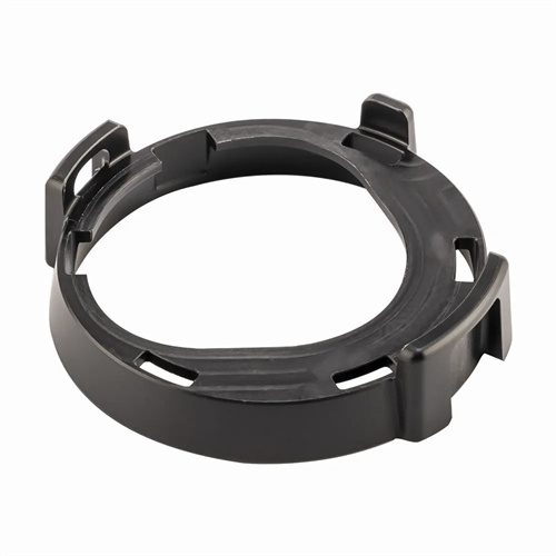
Core venting is key to addressing gas accumulation at the bottom of deep, cylindrical parts. This requires a specialized venting structure designed into the core. The cores for deep, cylindrical parts are typically cylindrical, making it easy for air pockets to form in the corners during melt filling. Radial venting grooves radiating from the center, 3-5mm wide and 0.02-0.04mm deep, can be designed into the core’s bottom. These grooves connect to the venting grooves on the parting surface, creating a venting channel. For deep, cylindrical parts with a central hole, an axial vent hole with a diameter of 3-5mm can be placed in the center of the core. This venting hole, combined with the radial venting grooves at the bottom, allows gas to escape from the center. Core venting can also be achieved using a spliced core structure, dividing the core into two halves, with a 0.01-0.02mm gap at the joint surface to provide an venting channel. This ensures effective venting while minimizing the appearance of the finished product. For example, a combination of four radial venting grooves and a central vent hole at the bottom of the core for a deep, cylindrical motor housing improves bottom gas venting efficiency by 40%, resolving the persistent problem of bottom bubbles. When venting the core, care must be taken to avoid the exhaust groove affecting the dimensional accuracy of the product. In particular, the depth of the exhaust groove on the mating surface must be strictly controlled to prevent flash.
Ejector-assisted venting is a supplementary method for venting deep-cylinder plastic parts, utilizing the clearances within the ejector components to expel residual gas. Deep-cylinder plastic parts are typically ejected using an ejector plate or ejector tube. A clearance of 0.01-0.02mm can be reserved between the ejector plate and the core, while the clearance between the ejector tube and the core should be controlled at 0.015-0.03mm. These clearances serve as venting channels during the ejection process, discharging residual gas between the core and the part. For deep-cylinder molds using a push plate, an annular venting groove can be created on the push plate, connecting to the venting groove at the bottom of the core to form a venting network. The ejector mechanism’s venting must be coordinated with the ejection action. Initially, the gap opens to expel gas, preventing gas from being trapped between the part and the mold, leading to deformation. For example, a deep-cylinder cosmetic bottle mold using a push plate ejector successfully vented gas between the bottle base and the core by controlling the clearance between the ejector tube and the core to 0.02mm, reducing the incidence of bottom sink marks from 30% to below 5%.
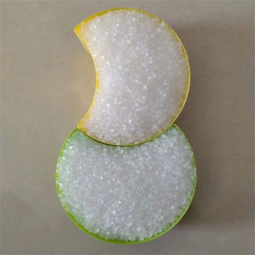
Optimizing process parameters significantly impacts the venting performance of deep-barrel plastic parts, requiring adjustment to minimize gas accumulation. Appropriately increasing the melt temperature (e.g., from 190°C to 210°C for PP) can reduce melt viscosity, improve fluidity, and facilitate gas flow and discharge. However, excessively high temperatures can cause plastic degradation and generate more gas, so they must be kept within a reasonable range. A staged injection speed should be employed: initially, a low injection speed (30-50 mm/s) ensures the melt fills the bottom smoothly and avoids turbulent air entrainment. In the middle, a moderate injection speed (50-80 mm/s) propels the melt upward along the barrel wall. Finally , a high injection speed (80-120 mm/s) ensures rapid filling of the barrel opening and minimizes gas retention time. Increasing injection and holding pressures can enhance melt penetration and compress gas into the venting grooves for discharge. However, excessive pressure should be avoided, which can lead to flash. Appropriately extending the holding time ensures adequate melt filling, compensates for shrinkage, and reduces vacuum bubbles caused by shrinkage. Mold temperature control is also crucial. Increasing the mold temperature (e.g., from 50°C to 70°C) can slow melt cooling and facilitate gas discharge, especially for highly crystalline plastics. By optimizing process parameters and exhaust structures, we can maximize exhaust efficiency and ensure the molding quality of deep-cylinder plastic parts.