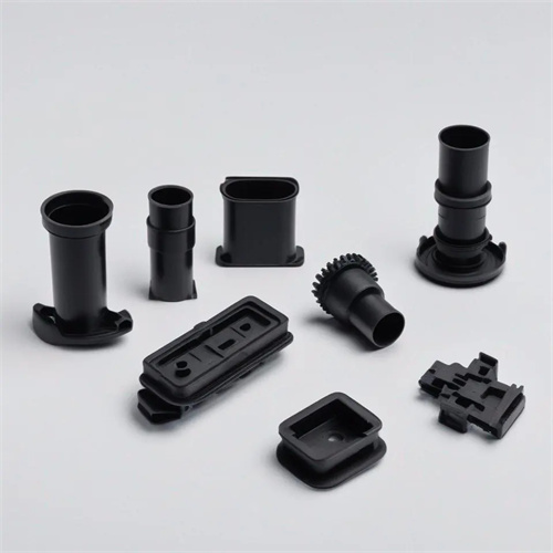
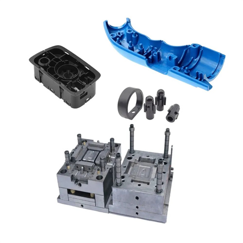
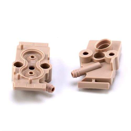
Injection Molding Water Ripples and Solutions
Injection molding water ripples are a common surface defect in products. They appear as wavy stripes distributed along the direction of melt flow, resembling ripples on the water surface. They seriously affect the visual effect and surface finish of the product, and are especially noticeable in light-colored or transparent products. The generation of water ripples is closely related to factors such as the flow state of the melt in the mold cavity, the cooling rate, and the characteristics of the raw materials. They are usually caused by the melt front cooling too quickly, forming a solidified layer after contact with the mold cavity surface, and the subsequent melt pushing the solidified layer to produce wrinkles. Solving the water ripple problem requires improving the melt fluidity, optimizing the cooling conditions, adjusting the mold structure, and other aspects. Through comprehensive measures, defects can be eliminated and the appearance quality of the product can be improved.
Insufficient melt flowability is the primary cause of water ripples, and melt flow properties need to be improved by adjusting raw materials and process parameters. Regarding raw materials, choose plastic grades with a higher melt flow rate (MFR). For example, when processing PP products, a grade with an MFR of 20g/10min is less likely to cause water ripples than one with an MFR of 5g/10min. This is because the melt has lower viscosity and less flow resistance, allowing it to quickly fill the mold cavity. If low-MFR raw materials are necessary, adding an appropriate amount of plasticizer or flow modifier can improve melt flowability. For example, adding 5%-10% dioctyl phthalate (DOP) to PVC can improve melt flowability. Regarding process parameters, increasing the barrel temperature is an effective way to improve flowability. For example, increasing the barrel temperature from 180°C to 200°C for PE and from 220°C to 240°C for ABS can significantly reduce melt viscosity. However, care should be taken to avoid excessively high temperatures to prevent plastic degradation. For example, the maximum barrel temperature for PC should not exceed 300°C. Properly increasing the back pressure (from 5 bar to 10-15 bar) can make the raw materials plasticized more uniformly, increase the melt density, improve the fluidity, and reduce the generation of water ripples.
An improperly designed cooling system can exacerbate water ripple defects. The mold temperature and cooling water path layout need to be optimized to slow the cooling rate of the melt. Excessively low mold temperature is the primary cause of rapid solidification at the melt front. The mold temperature should be raised to bring the cavity surface temperature close to the plastic’s glass transition temperature to minimize the formation of a solidified layer. For example, increasing the mold temperature from 30°C to 50-60°C when processing PP products, and from 60°C to 80-100°C when processing PC products, can effectively reduce water ripples. Mold temperature uniformity is also crucial. The temperature difference across the cavity must be kept within ±3°C. This can be achieved by increasing the number of cooling water paths and optimizing their layout. For example, independent water paths can be added to areas with uneven wall thickness to prevent localized low temperatures. For large products, a hot oil temperature control system can replace traditional cooling water to precisely control the mold temperature and ensure good melt fluidity during the filling process. The cooling time needs to be set reasonably. It should not be too short to avoid appearance defects caused by incomplete shaping of the product, but it should not be too long to affect production efficiency. It needs to be determined according to the thickness of the product and the characteristics of the plastic, usually 10-60 seconds.
Optimizing injection process parameters is crucial to eliminating moire. Adjusting injection speed, pressure, and stroke is crucial to improving melt flow. A segmented injection method, known as “slow start, fast fill,” is employed: Initially, injection is performed at a low speed (30-50 mm/s) to ensure smooth melt entry into the cavity, avoiding uneven cooling caused by turbulence. Once the melt covers the bottom of the cavity, the injection speed is increased (80-120 mm/s) to rapidly fill the cavity and minimize cooling time during the melt flow. Injection pressure must be sufficiently high to ensure the melt has sufficient momentum to overcome flow resistance and propel the leading edge forward, avoiding melt stagnation and cooling caused by insufficient pressure. Appropriate holding pressure and time are crucial. Holding pressure is typically 60%-80% of the injection pressure, and the holding time is set based on the thickness of the part to ensure adequate melt shrinkage compensation, preventing surface depressions and moire caused by shrinkage. For example, a certain ABS shell product showed obvious water ripples during mold trial. By increasing the injection speed from 50mm/s to 90mm/s and the mold temperature from 50℃ to 70℃, the water ripple defects were completely eliminated.
Improving mold structure can fundamentally resolve the water ripple problem. This requires optimizing gate location, size, and cavity surface quality. Improper gate placement can result in a long or uneven melt flow path. The gate should be placed near the thickest part or in the center of the mold to shorten the flow distance and allow the melt to quickly fill the mold cavity. For example, for large flat products, multi-point pouring can be used to reduce melt flow time. An undersized gate can result in excessive shear rates during melt flow, leading to localized overheating and uneven cooling. Appropriately enlarging the gate size—for example, increasing the point gate diameter from 1mm to 1.5-2mm and the side gate width from 3mm to 5mm—can reduce shear rates and improve melt flow. Cavity surface roughness significantly affects water ripples. A rough surface increases melt flow resistance, leading to uneven cooling at the melt front. Polishing the cavity surface to an Ra of less than 0.4μm is necessary to reduce friction between the melt and the mold cavity, ensuring smoother melt flow. For products with complex shapes, rounded corners can be set at the turning points of the melt flow to avoid melt retention and cooling caused by right angles and reduce the generation of water ripples.
Raw material pretreatment and environmental control can also help reduce water moiré defects. Ensure that the raw materials are thoroughly dried and highly clean. Hygroscopic plastics (such as PA and PC) require thorough drying: PA should be dried at 80-100°C for 4-6 hours, and PC at 120-140°C for 6-8 hours, reducing the moisture content to below 0.05%. This prevents melt viscosity fluctuations and bubbles caused by moisture, indirectly reducing water moiré. Impurities in the raw materials or an excessively high proportion of recycled material can affect melt uniformity, leading to poor flow and uneven cooling. The recycled material proportion should be controlled to no more than 20%, and the raw materials should be screened to remove impurities. The production environment should maintain stable temperature and humidity, ranging from 20-30°C and 50%-60%, to prevent moisture absorption by the raw materials or mold temperature fluctuations due to environmental changes. Raw material pretreatment and environmental control provide an excellent foundation for eliminating water moiré. Combined with process and mold optimization, this cosmetic defect can be effectively addressed.