Design of injection-molded wear-resistant blocks
Injection wear blocks are key components used to reduce wear on moving parts in molds. They are mainly installed in frequently moving areas such as guide pins, guide sleeves, and ejectors. Their wear resistance protects the main structure of the mold and extends the service life of the mold. During the injection molding process, mold components will generate continuous friction due to repeated opening and closing of the mold, and ejection and resetting. If protective measures are not taken, it is very easy to cause an increase in the fit clearance, a decrease in guiding accuracy, and even cause mold failure. Therefore, the design of wear blocks needs to comprehensively consider factors such as material selection, structural form, dimensional parameters, and installation method to ensure that they have sufficient wear resistance, strength, and adaptability. High-quality wear block design can not only reduce mold maintenance costs, but also improve production efficiency and product quality stability.
The material selection for wear blocks is central to their design, directly determining their wear resistance and service life. Common wear-resistant materials include alloy cast iron, bronze, powder metallurgy, and engineering plastics, each with its own specific application scenarios. Alloy cast iron offers high hardness and wear resistance, and is relatively inexpensive. It is suitable for applications with high loads but slow motion, such as sliding contact between mold plates. Bronze materials (such as tin bronze and aluminum bronze) offer excellent friction reduction and thermal conductivity, maintaining stable friction performance even without lubrication, and are commonly used for wear-resistant bushings in guide pins and guide sleeves. Powder metallurgy materials can be tailored to achieve varying properties through composition adjustment. Their high porosity allows them to retain lubricant, making them suitable for areas that require limited lubrication. Engineering plastics (such as polytetrafluoroethylene and polyoxymethylene) offer low friction coefficients and excellent corrosion resistance, making them suitable for lightly loaded, high-speed moving parts and preventing metal-to-metal seizure. Material selection requires a comprehensive assessment of the mold’s operating conditions, including load, motion speed, temperature range, and lubrication requirements. Friction and wear testing should be performed as necessary for verification.
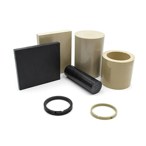
The structural design of wear blocks must meet the requirements of easy installation and reasonable frictional forces. Common structural forms include blocks, rings, and plates, and the design must be adapted to the shape and space of the installation location. For example, the wear block on the guide post is usually designed as a ring, with an inner hole that has an interference fit with the guide post and an outer diameter that has a clearance fit with the guide sleeve to ensure guiding accuracy during movement. The wear block between the ejector mounting plate and the moving platen is often a block, fixed to the platen with countersunk screws to avoid interference with the ejector. The following key points should be considered in the structural design: First, the thickness of the wear block should be appropriate. Too thin will cause rapid wear, while too thick may affect the fit of the components . Second, corners should be chamfered to prevent scratches on other parts or operators during installation. Third, the surface roughness of the sliding friction surface must be maintained below Ra0.8μm to reduce frictional resistance and wear rate. In addition, wear blocks that withstand lateral forces can be designed with stepped structures or positioning bosses to improve installation stability and prevent displacement during operation.
Determining dimensional parameters is a crucial step in the design of wear-resistant blocks, and calculations must be made based on the motion trajectory and stress conditions of the mold components. The length of the wear-resistant block should cover the maximum travel of the component to ensure wear protection throughout the entire motion process. For example, if the ejector moves 50mm during ejection and resetting, the corresponding wear-resistant block length should be no less than 50mm to avoid wear in local areas due to lack of protection. The width and height must be determined based on the installation space and the load-bearing area to ensure that the pressure per unit area is within the allowable range of the material and to prevent deformation or breakage of the wear-resistant block due to overload. For annular wear-resistant blocks, the inner diameter and the diameter of the mating shaft are fitted with an interference fit, with the interference fit generally being 0.01-0.03mm to ensure secure assembly. The outer diameter and the mating hole are fitted with a clearance fit, with the clearance determined based on the motion accuracy requirements, typically 0.01-0.05mm. When designing wear-resistant blocks for large molds, the effects of thermal expansion and contraction must also be considered, and appropriate clearance must be reserved to avoid sticking caused by temperature changes.
The installation method and lubrication design of wear blocks have a significant impact on their performance. The installation method must ensure that the wear blocks are accurately positioned and securely fixed. Common methods include screw fixation, interference fit, and adhesive fixation. Screw fixation is suitable for block-shaped wear blocks. Threaded holes or countersunk holes must be machined on the wear blocks. The specifications and number of screws are determined according to the size of the wear blocks and the amount of force applied to them to ensure that they will not loosen due to vibration. Interference fit is suitable for annular wear blocks. The wear blocks are pressed into the mounting holes using a press. It is suitable for situations requiring high coaxiality. Adhesive fixation is suitable for small or non-stressed wear blocks. High-strength epoxy resin glue is used for fixation. It is easy to operate but has a low load-bearing capacity. In terms of lubrication design, for metal wear blocks, lubrication grooves or oil holes must be set up and lubricating oil or grease must be added regularly to form an oil film to reduce friction and wear. For self-lubricating materials (such as oil-containing powder metallurgy and polytetrafluoroethylene), although they can operate under non-lubricated conditions, regular cleaning of surface impurities can still extend their service life. In addition, during installation, ensure that the wear block is aligned with the center line of the mating component to avoid eccentric loading, which may lead to increased local wear.