Fixed mold push rod and movable mold push rod composite demoulding
Combined demolding using both fixed and movable mold ejectors is a highly efficient demolding method for complex-shaped plastic parts. By employing ejector mechanisms on both the fixed and movable molds, this method solves the demolding challenges of parts with deep cavities, undercuts, or large surfaces, which are difficult to handle with traditional single-directional demolding. This combined demolding mechanism balances the forces acting on the part during demolding, reducing deformation or damage caused by unilateral ejection. It is particularly suitable for large, complex parts such as automotive parts and appliance housings. For example, a car instrument panel, due to multiple undercuts and deep cavities, exhibited severe deformation when demolded using a single movable mold ejector. By switching to a combined demolding method using both fixed and movable mold ejectors, the deformation was reduced from 1.5mm to 0.3mm, and the yield rate increased to 99%. The key to combined demolding lies in coordinating the sequence and force of the fixed and movable mold ejectors to ensure a smooth release of the part from the cavity and core. Its design requires comprehensive consideration of the part structure, mold type, and production efficiency.
The structure of the combined ejector system for the fixed mold and movable mold includes a fixed mold ejector system, a movable mold ejector system, a sequential control mechanism, and a guide positioning device. The fixed mold ejector system is installed on the fixed mold side and consists of a fixed mold ejector, an ejector fixing plate, an ejector plate, and a drive device (such as a spring or cylinder). It is primarily used to push the plastic part out of the fixed mold cavity. The movable mold ejector system is installed on the movable mold side and has a structure similar to a traditional ejector mechanism, including a movable mold ejector, an ejector plate, and an ejector cylinder. It is responsible for ejecting the plastic part from the core. The sequential control mechanism is key to the combined ejection process. It controls the movement sequence of the fixed and movable mold ejectors through a travel switch, hydraulic valve, or mechanical baffle. Three modes are typically selected: “fixed mold ejection first,” “movable mold ejection first,” or “synchronous ejection.” For example, for parts that fit tightly within the fixed mold cavity, a “fixed mold ejection first” mode is used. The fixed mold ejector moves first, pushing the part 0.5-1mm away from the cavity, before the movable mold ejector ejects it. For parts with deep cavities, a “synchronous ejection” mode is required to prevent deformation caused by unilateral force. Guide and positioning devices (such as guide pins and guide sleeves) ensure smooth movement of the fixed and movable mold ejector pins, preventing jamming or deviation.
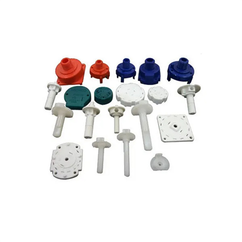
The design of the composite demolding mechanism requires determining the distribution and size of the push rods based on the structure of the plastic part. The diameters of the fixed mold push rods and the movable mold push rods must be determined based on force calculations. Typically, the diameter is ≥5mm. For large plastic parts, the push rod diameter can be increased to 8-12mm, with spacing controlled at 50-100mm to ensure uniform force. The contact point between the push rods and the plastic part should avoid the exterior surface and weak areas, with priority given to higher-strength areas such as ribs and bosses. The positions of the fixed mold push rods and the movable mold push rods must be staggered to avoid interference. For example, a washing machine inner barrel plastic part (500mm diameter) has eight 8mm diameter push rods on the fixed mold side, distributed along the edge of the barrel mouth; and twelve 6mm diameter push rods on the movable mold side, distributed at the bottom of the barrel and at the ribs. Smooth demolding is achieved through synchronous ejection. For plastic parts with undercuts, a tilted ejector or core-pulling mechanism can be integrated into the fixed mold or movable mold ejector system to complete the core-pulling action first, and then perform ejection. For example, the tilted ejector on the fixed mold side first pulls out the undercut, and the fixed mold ejector and movable mold ejector then eject the plastic part synchronously.
The design of the composite demolding mechanism’s motion flow must meet the requirements of both efficiency and safety. It is typically divided into four phases: mold opening, sequential ejection, removal, and reset. During the mold opening phase, the mold opens from the closed mold state. When the mold opening distance reaches the set value (usually 1.5-2 times the height of the plastic part), the sequential control mechanism issues a signal. During the sequential ejection phase, the fixed and movable mold pushers operate sequentially according to a preset pattern, completely ejecting the part from the mold. During the removal phase, the part is removed manually or by a robot. During the reset phase, the fixed and movable mold pushers are reset by springs or hydraulic cylinders, awaiting the next mold closing. The timing of these actions must be precisely controlled. The ejection time for a single set of pushers is typically 0.5-1 second, and the total composite ejection time is controlled within 2-3 seconds to avoid impacting production efficiency. For example, a two-cavity TV housing mold has an ejection time of 0.6 seconds for the fixed mold pusher and 0.8 seconds for the movable mold pusher, for a total ejection cycle of 2.5 seconds, meeting a production pace of 15 molds per minute. Furthermore, a safety interlock device is required to prevent the mold from closing if the pusher has not fully returned to its original position, preventing damage to the component.
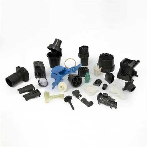
The application and debugging of composite demolding mechanisms require attention to several key points. In terms of application scenarios, they are suitable for large, complex plastic parts, deep-cavity plastic parts, plastic parts that fit tightly within the mold cavity, and molds with multiple parting surfaces, such as two-shot molds and stacked molds. During the debugging phase, the push rod movement must be manually tested to check for interference or jamming, ensuring that the motion trajectories of the fixed and movable mold push rods do not intersect. During mold trials, the ejection pressure and speed are gradually adjusted. The pressure of the fixed mold push rod is typically 5-10 MPa, and the pressure of the movable mold push rod is 10-15 MPa. The speed is controlled at 10-20 mm/s. Observe whether the plastic part is demolded smoothly and whether there is any deformation or damage. If the plastic part becomes stuck between the fixed and movable molds, adjust the ejection sequence or increase the ejection distance. If white ejection occurs, optimize the push rod distribution or reduce the ejection pressure. During routine maintenance, regularly clean debris from the push rods and guide holes, add lubricating oil, and check the sensitivity of the sequence control mechanism to ensure accurate movement. Through reasonable design and debugging, the composite demoulding of fixed mold push rod and movable mold push rod can effectively solve the demoulding problem of complex plastic parts and improve production efficiency and product quality.