Installation of the second-plate sliding foot (pad iron) support mechanism
The second-plate slide (shim) support mechanism is a critical connection between the movable mold and the injection molding machine worktable. Its primary function is to support the mold’s weight, adjust the mold’s levelness, and guide the movable mold’s smooth movement during mold opening and closing. This ensures precise alignment between the mold and the injection molding machine, preventing mold deformation or part defects caused by uneven force. In large injection molds (weighing > 5 tons) or precision molds, the installation accuracy of the slide (shim) support mechanism directly impacts production stability. For example, a certain automobile bumper mold experienced misalignment of the cavity during mold closing due to tilted slide installation, resulting in severe flash. Adjusting the slide’s levelness completely eliminated the flash defect. The installation of this mechanism adheres to strict procedures and precision requirements, including benchmark positioning, leveling, tightening, and operational testing to ensure that the mold’s workload and motion requirements are met.

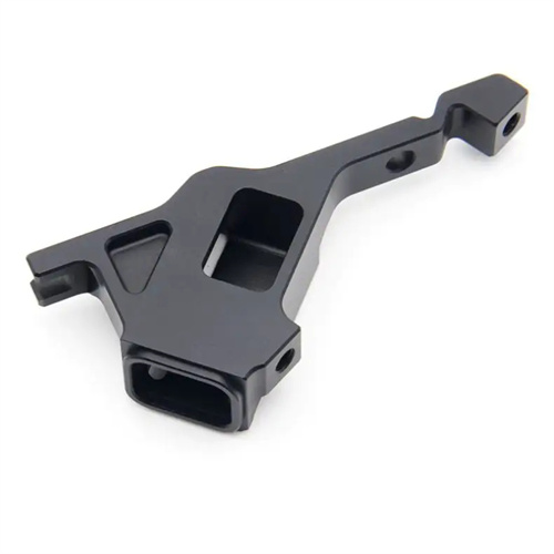
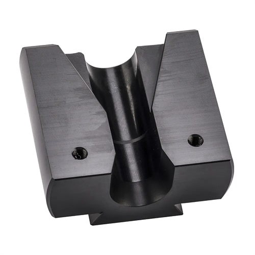
The second-plate runner (shim) support mechanism consists of the runner body, adjustment shims, fastening bolts, and guide bars. The selection of each component is determined based on the mold weight and size. The runner body is typically made of HT300 gray cast iron or Q235 steel, with a rectangular or L-shaped cross-section. Its length is determined by the mold’s moving platen size, generally 1/3-1/2 the length of the moving platen. For example, a 4-meter-long moving platen requires two 1.5-meter-long runners. Adjustment shims are available in fixed and adjustable configurations. Fixed shims provide basic support, while adjustable shims (with bolt adjustment) are used for precise leveling. Shims are made of 45# steel with a surface hardening treatment (hardness 40-45 HRC) for excellent wear resistance. Fastening bolts are high-strength bolts (grade 8.8 or 10.9), with a diameter determined by the runner size (typically M16-M24), ensuring a secure connection. The guide bar is installed on the side of the slide and cooperates with the guide rail of the injection molding machine workbench. The material is wear-resistant cast iron or bronze to ensure smooth movement of the movable mold. The guide clearance is controlled at 0.05-0.1mm.
Preparatory work for the installation of the second platen runners (shims) is crucial. Ensure that the installation base and tools meet the requirements. First, clean the injection molding machine worktable and the bottom of the mold’s movable platen from oil, iron filings, and other debris. Use a spirit level to check the worktable’s levelness. If the deviation exceeds 0.1mm/m, adjust the levelness using the injection molding machine’s anchor bolts. Then, according to the mold design drawings, mark the runner installation lines on the bottom of the movable platen. The runners should be symmetrically distributed on both sides of the mold’s center of gravity, at least 100mm from the mold edge to ensure balanced force. For example, for a 10-ton mold, two runners should be installed symmetrically on the bottom of the movable platen, each supporting 5 tons of weight. They should be spaced 2 meters apart and aligned with the mold’s center of gravity. Prepare installation tools, including a torque wrench (range 0-500N · m ), a spirit level (accuracy 0.02mm/m ), a dial indicator, and feeler gauges to ensure accurate measurement and tightening. For large molds, use a crane or forklift to assist in lifting to prevent damage during installation.
The installation steps for the second-plate runners (shims) must strictly follow the sequence of positioning, adjustment, and tightening. The first step is positioning the runners. Place the runners at the marked positions on the bottom of the moving platen and secure them with dowel pins or temporary spot welds, ensuring a parallelism error of ≤0.1mm between the runners and the platen edge. The second step is leveling. Place a level at each end of the runners and adjust the height using the bolts on the adjustable shims to maintain a level error of ≤0.05mm/m. The height difference between multiple runners in the same mold should be ≤0.03mm, ensuring overall mold leveling. For example, when adjusting the runners of a precision mold, first perform coarse adjustments to reduce the level error to within 0.1mm/m. Then, use a dial indicator to precisely measure and fine-tune to 0.03mm/m to meet high-precision mold clamping requirements. The third step is tightening. Tighten the bolts evenly diagonally, using the torque value determined by the bolt specification ( 300-350N · m for M20 bolts ). Ensure consistent preload on each bolt to prevent runner deformation. After tightening, check the level again. If there is any deviation, readjust it until it meets the requirements.
Post-installation inspection and maintenance of the second-plate runner (shim) is crucial for ensuring long-term stable operation. After installation, conduct a no-load run test. Manually slide the movable mold on the injection molding machine worktable to check for any sticking or unusual noise. The sliding resistance should be uniform and free of significant fluctuations. Then, install the mold and conduct trial production. Observe the molded part for defects such as flash and dimensional deviations. If any defects are found, recheck the levelness and tightening of the runner. During routine maintenance, regularly clean debris from the contact surface between the runner and the worktable. Lubricate with lubricant (such as lithium-based grease) monthly to maintain smooth sliding. Regularly check the torque of the fastening bolts to prevent loosening. Check every 1,000 molds and tighten immediately if any looseness is detected. For runners used for extended periods, inspect the surface for wear. If the wear depth exceeds 0.5mm, replace the runner or perform a weld repair to ensure support accuracy. Additionally, place blocks under the runner when storing the mold to prevent rust from direct contact with the ground. Upon reinstallation, recheck the levelness to ensure compliance. Through standardized installation and maintenance, the second-plate sliding foot (pad iron) support mechanism can effectively ensure the stable operation of the mold, extend the service life of the mold, and improve the quality of plastic parts.